
31 Oct Tech Tip Tuesday: How does a control box power stabilization legs?
A control box is used to drive stabilization legs or hydraulic landing gear. It’s a self-contained set of controls that includes a motor or pump, reservoir, and valves to operate the landing gear. The control box supplies high pressure hydraulic energy to extend the legs or lift the trailer and low hydraulic pressure to retract the legs.
Combined with Power-Packer landing gear or stabilization legs, the control box uses air pressure from the emergency brakes or another source to generate pressure up to 3000 psi. The booster pump in our system converts 75 psi of air pressure to 3000 psi of hydraulic lift capacity with our 40:1 pilot ratio.
Types of control boxes
Power-Packer makes two types of control boxes, and both systems each generate 2,500 psi. The difference is in how the booster valve operates:
- Standard – A handle is used to manually pump the stabilization or jack legs into position.
- Auto-boost – Simply press a button and the system extends the stabilization legs or landing gear automatically, saving time and preventing injuries.
Control box part description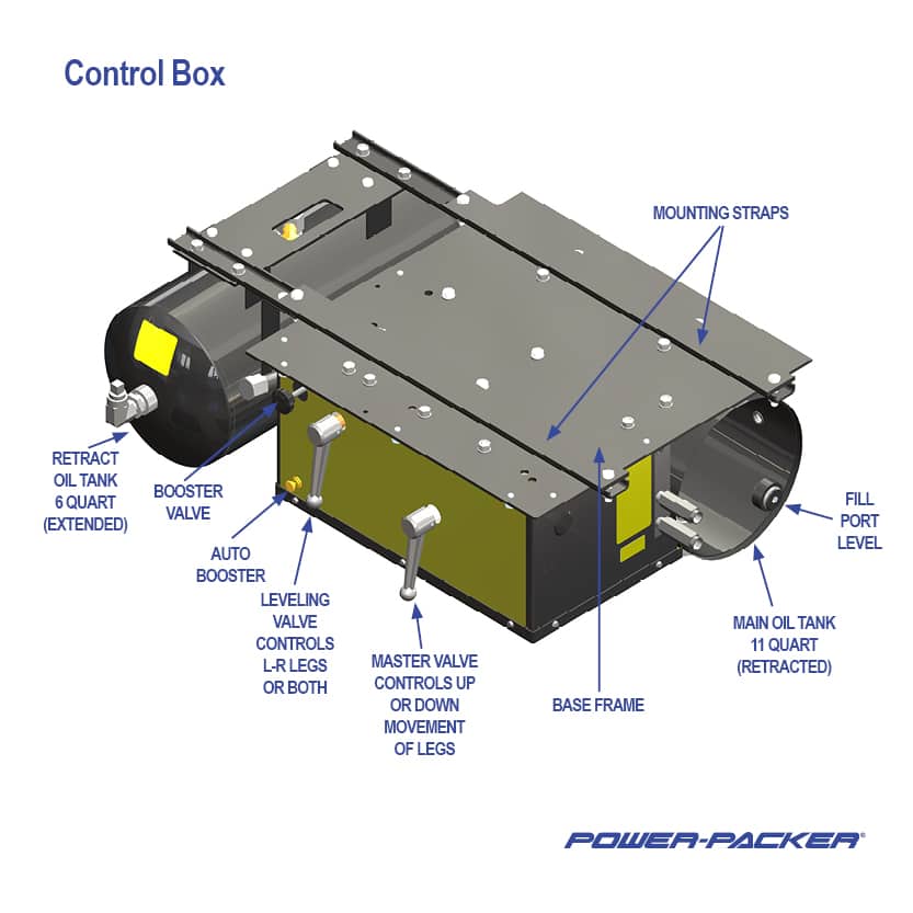
Two levers on the front of the control box control the master and leveling valves. The master control valve has two parts, the air piston side and the oil return block. The master valve extends or retracts the legs. The leveling valve adjusts for uneven ground or load conditions, allowing the operator to extend or retract both legs at the same time or one side individually. The booster pump transforms the energy that changes low pressure air into high pressure hydraulic energy to extend the legs. The booster valve cycles the booster pump. It is cycled manually by pushing and pulling the manual booster handle on the standard control box. On the auto-boost control box, it cycles automatically with the logic valve. It can also be cycled manually by pushing and pulling the booster valve handle on the front of the auto-boost control box. The main oil tank stores and pressurizes the oil used to extend the legs, and the retract oil tank stores and pressurizes the oil used to retract the legs.
The main oil tank in the control box holds 11 quarts of oil when the legs are retracted, and the retract tank holds 6 quarts of oil when the legs are extended. Both tanks come with a fill port to ensure the proper oil level. Mounting straps help you easily install the system onto the truck’s frame.
Controlling the system
With the auto-boost control boxes, there are two levers and a button to operate the system. The master valve lever controls leg movement. The leveling valve allows the user to raise the legs separately or simultaneously. Based on the position of the leveling valve, the auto-boost button will extend or retract the legs once pressed.
How the system works
To best explain circuit operation, assume that both legs are at mid stroke. Turning the master control valve as far counterclockwise as it will go puts the master valve in the “legs retract” mode. In this position, any air pressure in the main oil tank is vented out through the air portion of the master valve. Air pressure from the emergency air brake line is connected to the retract oil tank by the air portion of the master valve. In the retract tank, the air pressure forces oil out to the bottom or retract port of the legs, causing the legs to retract. Oil returning from the top port or extended side of the legs comes in through the leveling valve. By turning the leveling valve handle one way or the other, either leg may be partly or completely stopped.
Oil flows out of the leveling valve to the booster valve, and to the oil return block in the master valve. At the booster pump, the oil is stopped from flowing by one of the ball checks in the booster nozzle, but the oil can flow in the master valve and return to the main oil tank. By moving the master valve handle slightly clockwise, it is possible to slow the legs down as they retract. When the legs are fully retracted, the air pressure in the retract tank will hold the legs up. The master valve should always be in the over-the-road travel position.
Extending the stabilization legs
Rotate the master valve handle clockwise as far as it goes. Air pressure inside the retract oil tank vents out through the air portion of the master valve. Air pressure from the emergency air brake line is connected to the booster valve and the main oil tank. The oil return passage in the master valve is blocked with the master valve in the legs-extended position, and oil cannot flow through it (flow travels through booster nozzle).
The legs travel rapidly to the ground. At low pressure, no boosting is necessary. The “legs extended, rapid to ground” oil flows from the main oil tank to the booster nozzle. The booster nozzle has two ball checks. The bottom check allows oil to flow into the booster but not out. The top ball check allows oil to flow out but not in. This combination allows oil to flow through the booster nozzle to the leveling valve, and to the legs. The leveling valve handle may be turned one way or the other to slow down or completely stop either stabilization leg. Oil from the “retract” side of the leg returns to the retract oil tank as the legs extend.
Lifting a trailer
Once the legs reach the ground, air pressure alone is not enough to lift a trailer. The booster pump must be cycled to lift it. Press and hold the logic valve (auto-boost control box) until the trailer is raised to the desired height. If the automatic system malfunctions, release the logic valve and repress. If the automatic system still does not function, or if manual operation is desired, the booster valve may be cycled manually by pushing and holding the power valve in and repeatedly pulling the power valve out until the trailer reaches the desired height.
Periodically, the power valve (black knob) may stick. To correct, push and pull the knob out and continue to push the logic valve. As the logic valve is pushed the following occurs:
- The blind or back end of the booster is vented out.
- Oil, under air pressure from the main tank, enters the booster nozzle and pushes the piston rod back.
- The top ball check in the nozzle keeps oil in the legs from backing up into the nozzle.
- Air pressure is applied to the large area of the booster piston.
This large volume of low-pressure air forces the piston and rod assembly forward into the nozzle, forcing a small volume of high-pressure oil out of the nozzle, through the leveling valve and to the legs. This cycle may be repeated as many times as needed to raise the trailer to the desired height. To lower the trailer or retract the legs, slowly move the master valve handle counterclockwise as far as it will go as previously noted.
Operating instructions are printed on the front of each control box. If you have questions about the Power-Packer control box or the right stabilization legs for your application, contact our Customer Service team at info@powerpackerus.com.