
29 Aug Tech Tip Tuesday: How to install a Power-Packer stabilization system
Power Packer offers control boxes as hydraulic power units for our stabilization legs because they allow for a self-contained stabilization circuit. The following instructions and part lists provide a helpful guide for installation of your stabilization system.
For all orders, start by checking your shipment to be sure there has been no damage or loss in shipping. Refer to the packing list, included in the hardware kit.
3.5- or 4-inch bore stabilization leg installation
Front mount legs
- Remove manually operated stabilization legs (if applicable).
- Install stabilization legs to standard leg mounting base. Allow 8-12 inches, or similar to the legs you have removed for ground clearance 12 inches of ground clearance with legs fully retracted. Use 5/8- to 18-inch, UNF grade 5, hex-head cap screws and hex nuts. Torque to 150 foot pounds.
Rear mount legs
- Determine the location for your stabilization legs. You should allow 6 inches of ground clearance (4 inches is the absolute minimum). Remember to allow for spring deflection when equipment is loaded.
- When designing a mounting structure, provide enough strength to lift the equipment and proper bracing to accommodate any side loading.
- Remove wheels if necessary. Cut a 6-inch channel to desired length (varies with equipment frame and leg stroke).
- Weld a 12-inch piece of 3/16-inch steel plate to the inside of the channel. These plates should be wide enough to place the center of the leg between the tires when the leg is mounted to the channel.
- Weld a loose mounting plate (supplied by Power-Packer) to the channel at the proper height, keeping in mind the preinstallation requirements.
- Weld a split collar half to the mounting channel where the bottom of the well tube will be located.
- Weld this fabrication to the trailer frame.
- Fabricate second leg mounting structure in the same manner.
- Mount legs using 5/8- to 18-inch, UNF grade 5 bolts. Torque to 150 foot pounds.
- Clamp remaining split collar halves in place with ½ to 20-inch UNF grade 5 bolts. Torque to 20 foot pounds.
Bracing
- The bottom of each leg must be braced to the equipment frame members in two directions, 90 degrees apart. These braces should not be welded to the leg. They may be mounted to the split collar, channel or the cross brace near the leg.
- Weld the cross brace from the bottom of one channel to the other.
- Weld a brace from the bottom of each channel to the trailer frame at a 45-degree angle. This brace should be pointed directly away from the leg.
- On each side, weld the bracing pointing forward or backward at a 45-degree angle from each channel on the cross brace to the equipment frame.
5- or 6-inch bore leg installation
Follow the same instructions as the 3.5- or 4-inch bore stabilization legs. Mount the legs to the structure using a minimum of 10, 5/8- 18-inch fasteners (grade 5 or better) on each side of the mounting plate. If two mounting plates are present, use a minimum of four, 5/8- 18-inch fasteners, (grade 5 or better) on each side of the lower mounting plate. Torque to 150 foot pounds (dry).
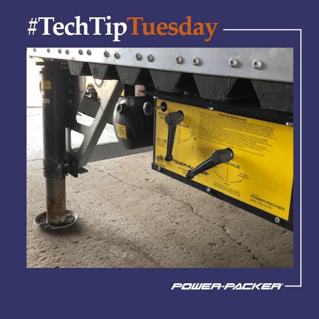
Control box mounting
- Determine desired control box location. No part of the control box or handles should extend beyond the sides of the equipment.
- Hold the control box in the desired location. Be sure cross members are free of rust and undercoating where control box hanger straps make contact.
- Tack weld hang straps in place. Remove Nuts from hanger straps and lower control box.
- Finish welding hanger straps to cross members and remount control box.
- Torque mounting bolts to 33 foot pounds.
Plumbing
Customers are responsible for supplying their own hoses. To determine the required length, we recommend:
- High-pressure hose
- Minimum of 5/16 inches
- Rated at 2,500 psi working pressure
- #6, 37-foot, SAE flare female swivel ends.
Note: These descriptions are one common way of installing rear-mount stabilizer legs and bracing systems. Other methods may be used based on the application.
This information applies only to Power-Packer products manufactured in North America. If you have questions about Power-Packer stabilization legs or difficulty finding a suitable mounting location, contact our Customer Service team at info@powerpackerus.com. Be sure to provide the serial and part numbers, located of the serial number plate on the control box cover, when ordering parts or requesting technical assistance.